
DIY for developers
Developer users can extend the capabilities of DIY by creating bespoke data models for hosting in the DIY cloud, and updating the data as it flows through the API.
Create a new data model
You can create your own data models in DIY, which will be hosted in the DIY cloud.
- In the API menu, select Models and click
 .
.
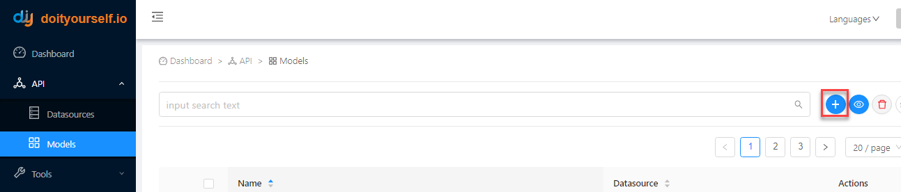
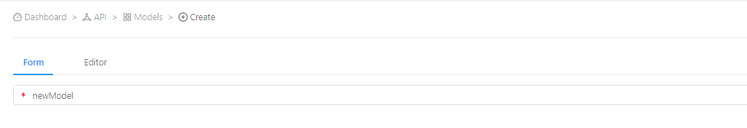
- Click the Form tab or Editor tab, then specify the model name (which must be unique and contain no spaces).
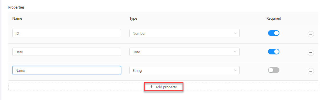
- For each of the required properties, click Add property, then specify the property name, data type and if it is required.
- Enable user access to your new model in the Default access control rules section, by selecting the type of user from the list and toggling the permission button to Allow. You can also click Add access control rules if you want to add more rules. Note that if you require more specific access control rules, you can create them using the Access control rules function.
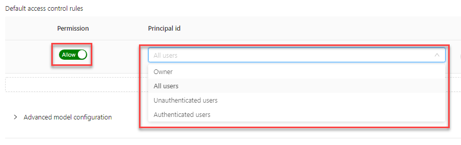
- Expand the Advanced model configuration section and specify database relations and endpoints.
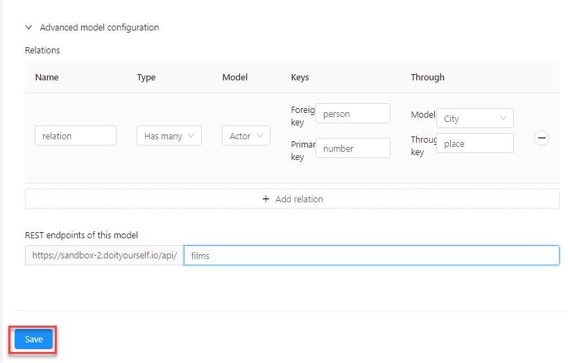
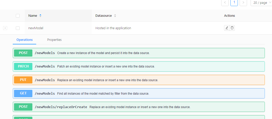
- Click Save. The model is now saved in the list, with the standard set of endpoints available in DIY.
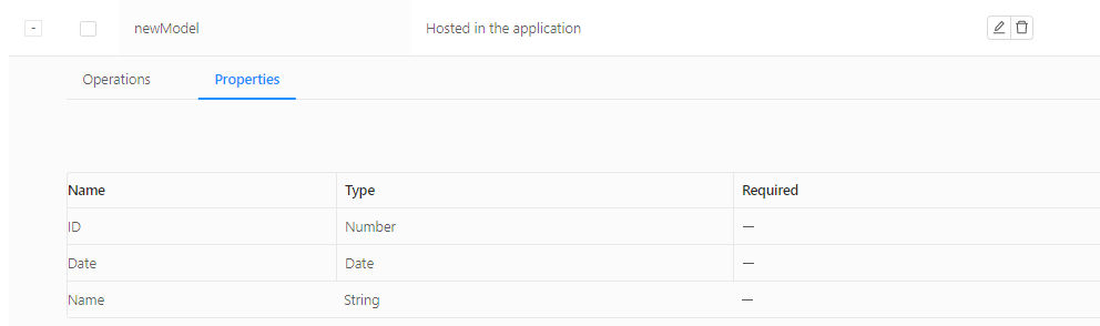
- Click the Properties tab to see the properties you defined.
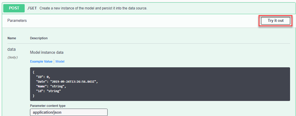
- Expand the endpoints and test them with the Try it out feature.
Make real-time changes to your API data flow
DIY includes a graphical tool for specifying changes to data as it passes through your DIY API flow, which are applied in real time when the API is called. You build your flow definition by connecting together different types of nodes, the building blocks of your API data, which come in different types:
- input and output nodes
- general function nodes
- DIY-specific nodes, including specific function nodes designed to interact with DIY data sources and models
Each node is a point where you can intercept the data during the flow and change it in some way. For example, if you want to transfer data from one database to another, you can change the format of the source data to suit the format of the destination database. By updating the nodes, not only can you change the format of your API's response data, but you can also redirect the data to, and pull data from, other services along the way.
See the Node reference at the bottom of this page for a description of all the nodes available.
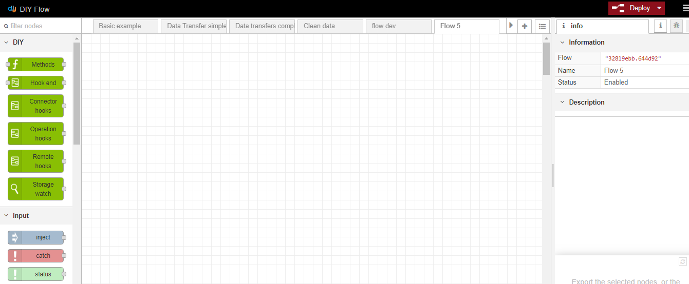
The tool
DIY's data flow tool is built on top of IBM's open source Node-RED application, which is a light-weight Node.js tool designed for creating data flows without the need for any coding, while still making it possible to create additional complexity with code, depending on your project's requirements. You can find more information about Node-RED:
- in this short video introduction
- in the Node-RED documentation
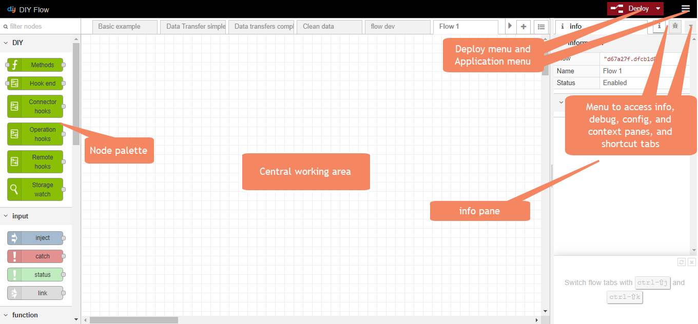
A brief summary of the tool's components is as follows:
- on the left, the node palette
- in the centre, a working area for your flow, into which you drag your nodes, connect them together and double-click on each node to specify its characteristics
- on the right, 4 different panes you can toggle between in a menu (the info and debug panes are also accessible from shortcut tabs):
- the info pane, giving context-specific information about the currently selected object -- the working area tab, the selected node, etc.
- the debug pane, showing the current debug information when the flow includes an output node of type debug
- the config pane
- the context pane
- at the top right, the Deploy menu, for deploying your finished flow, and the application menu, for all other application management functions.
A simple data flow
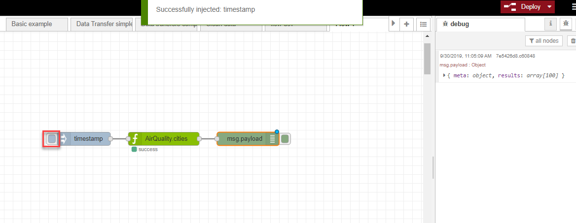
In this simple example, you can see a basic data flow, with a node representing the AirQuality API GET endpoint we created in our REST API connector video example. When we click the small tab on the left of the timestamp node to initiate the flow, the msg payload debug node displays the output from the flow in the debug pane.
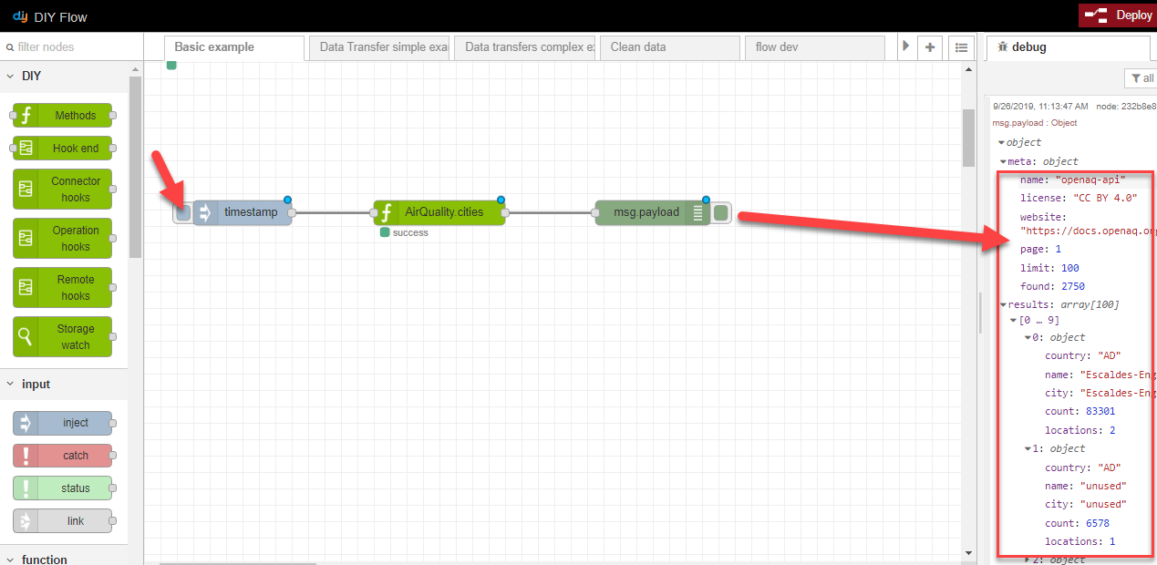
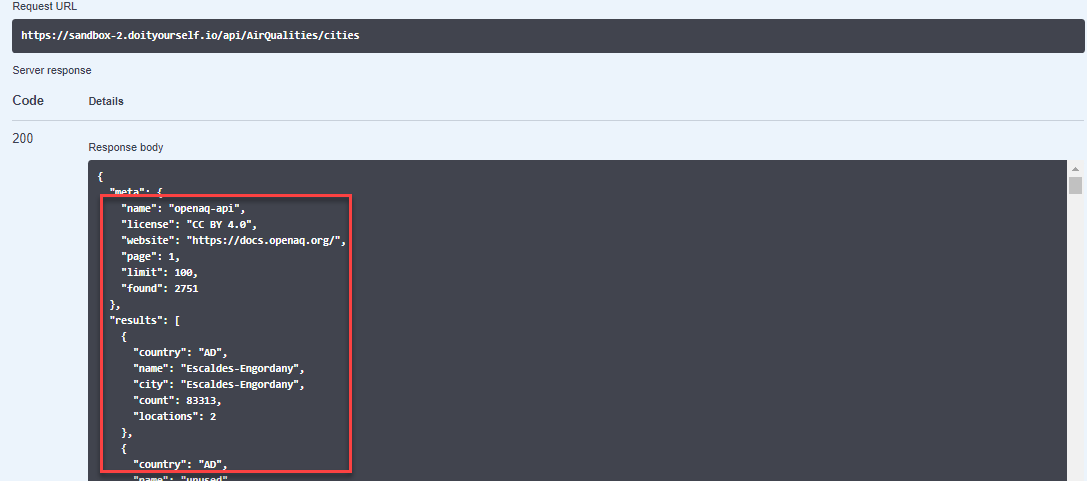
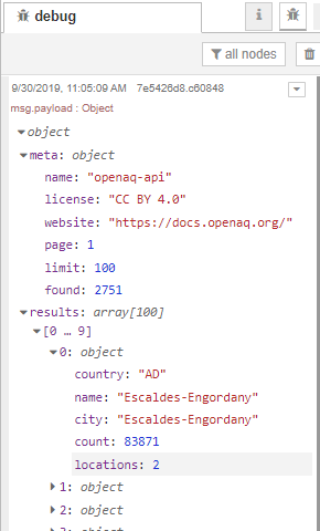
We haven't added any additional logic yet, so the query response output you see in the debug pane is exactly the same as the response you see when you click Try it out on the DIY Models page (see step 8 of the previous section):
Create a new data flow
We will now explain the basic steps for creating a new flow. Then we will show you some practical examples of flows you can create, that you can adapt to your own specific business case.
- In the Tools menu, click Flow.
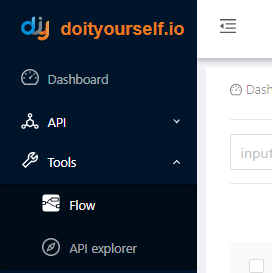
The graphical interface opens.
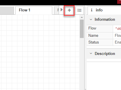
- Click the
 tab to create a new flow.
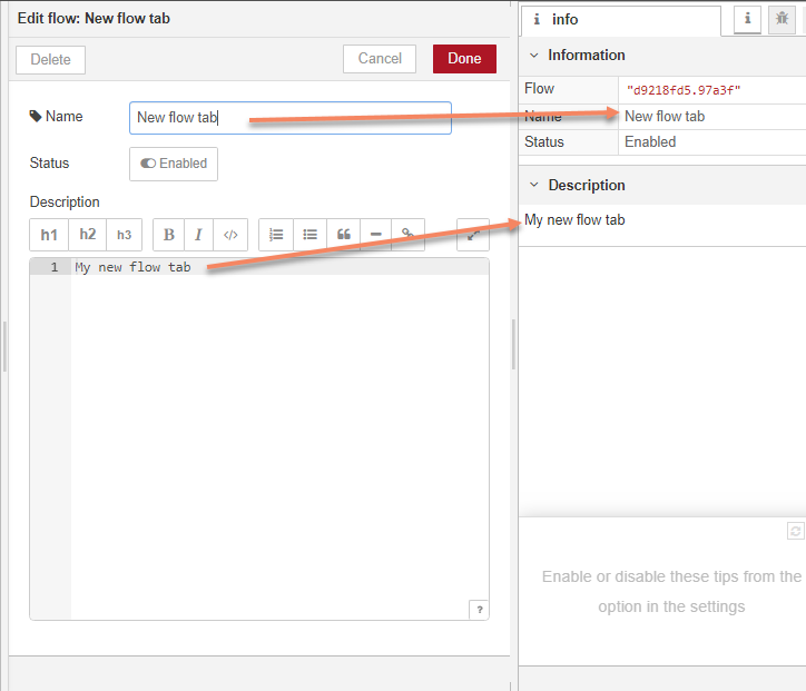
- Double-click the tab and give it a new name. Add a description if required, and click Done. The information is displayed in the info pane.
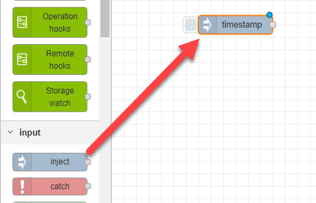
- In your new tab, drag your first node into the working area. All flows either begin with an input type node, which injects the data into the flow, or a DIY hooks node, which executes an operation on your data before injecting it into the flow. In this example we have dragged an inject node into the working area and left it as the default timestamp; this is the default node which injects the message payload into your flow.
Note that whenever you set the properties of a node, it is displayed with a new name reflecting those properties.
- Choose the next node of your flow, then click and drag between the connector dots of the two nodes to connect them together.
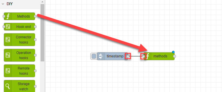
- Double-click on your second node and specify its properties, then click Done when you have finished.
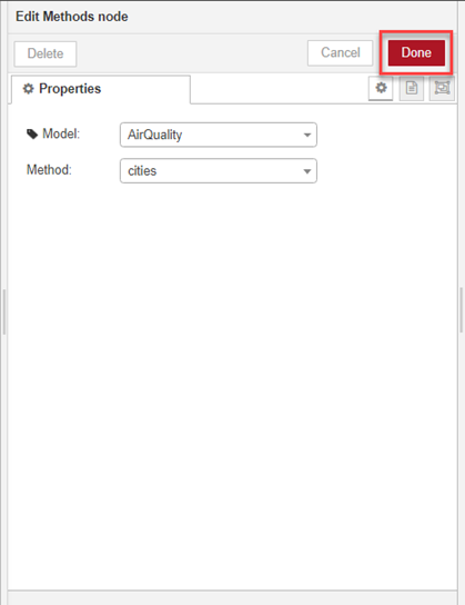
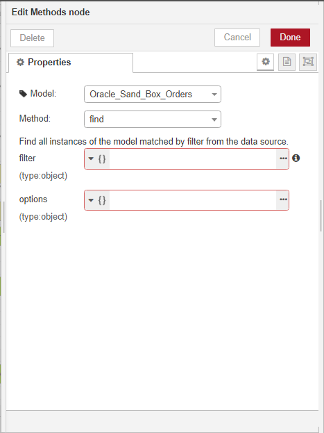
Note that in this example with the DIY Methods node, we do not have to run any additional methods on the data model to output data from it, since our model is a REST API GET endpoint and the GET method is defined as part of the data source itself. If we are working with a model such as an Oracle database, however, we need to specify a find method to output data from it.
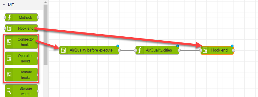
- Repeat steps 5 and 6 for all the other nodes you want to add to your flow. Note that if you started your flow with any of the DIY xxx hooks type nodes, you must also add a DIY Hook end in the flow to show where the hook operation ends.
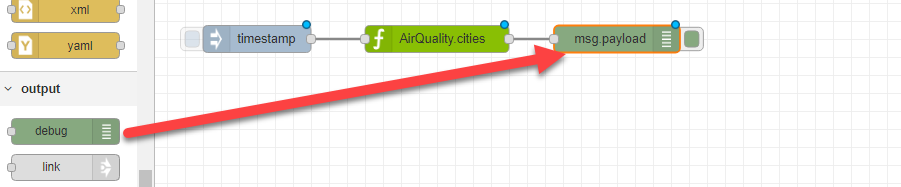
- To see your flow output in the debug pane, add a debug output node, leaving the default setting of msg.payload.
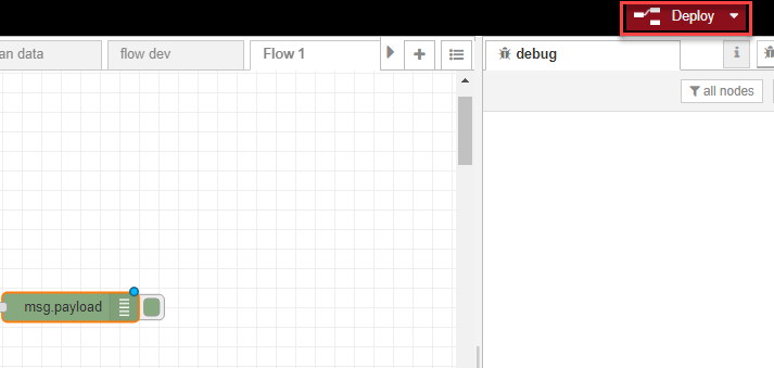
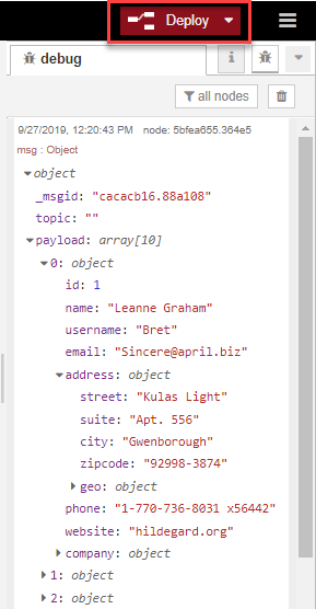
- Click Deploy to deploy your new flow.
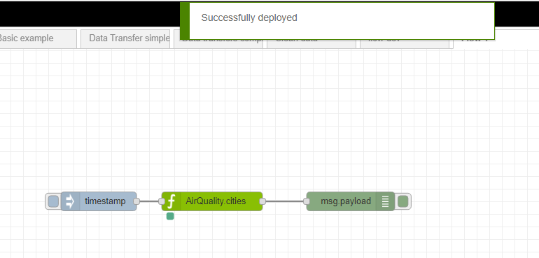
If your flow is:
- correctly specified, a Successfully deployed message is displayed, and any data flow changes will now be reflected in subsequent calls to the API:
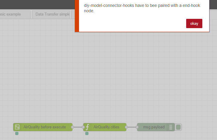
- incorrectly specified, an error is displayed (such as in this example where a Hook end node has not been specified with a DIY xxx hooks type node) and you need to correct the error before redeploying:
- Once successfully deployed, you can trigger your flow by clicking the tab on the left of the timestamp node and see the output message in the debug pane.
- Click the message to expand the different sections and see the field details.
Example 1
Extract data from a REST API data model, split the data up, transform it and insert it into an Oracle data model
In this example, we're going to retrieve contact data using a ContactPlaceHolder REST API GET contacts method, split the message up into individual contact records, and insert the records into the Oracle_Sand_Box_Customers data model table.
This example introduces the following concepts:
- the split node
- Node-RED TypedInput, used in DIY for selecting the type of input format for matching and mapping data
- the JSONata data transformation language, used in DIY for more complex data transformations
Before we begin
This example assumes the following data models were created in DIY:
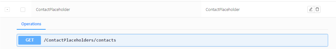
- a REST API called ContactPlaceHolder, with a GET contacts method:
- an Oracle data model called Oracle_Sand_Box_Customers:

Step 1 - Build the basic flow
First, we're going to drag in an inject node, leaving it with the default timestamp, and connect it to a DIY Methods node with a Model name of ContactPlaceHolder and a Method name of contacts. We'll add in a debug node at this point too, so we can already see our output.

Now let's go ahead and click the timestamp node and have a look at our output in the debug pane (not forgetting to deploy our flow first!).
We can see the format of our data doesn't match the format of the Oracle table we're inserting it into, so we need to introduce some new nodes to transform the data.
Step 2 - Split the data
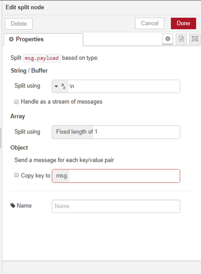
We're going to add a split node, to split each new line into a separate record.

We double-click on the node and specify the message is to be split into one message per table row.
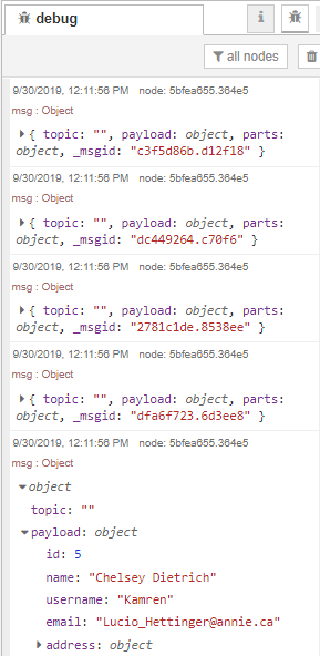
When we deploy our change and click the timestamp node, we can see the message has been split up.
Step 3 - Transform the data and insert it into the Oracle database
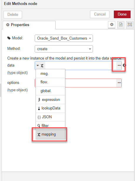
The next step is to add a new Methods node to map the message output from the split node to our Oracle database format, and insert the records into the Oracle database. We will need to apply some transformations along the way. We're going to use a create method, acting on the Oracle_Sand_Box_Customers data model.

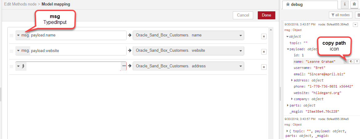
In the create method data menu we choose the mapping TypedInput type, then click the ellipsis button to open the editor.
We are going to map name, address and website, since we know these are the three fields which exist in both data models, so we create three new entries in the editor by clicking add three times.
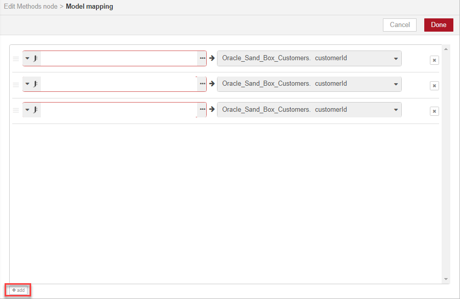
We choose msg as our TypedInput, then set each of the three fields to the values we want to map. We can copy the paths from the debug pane to the relevant fields in the message, by using the copy path icon and pasting the paths to the mapped fields.
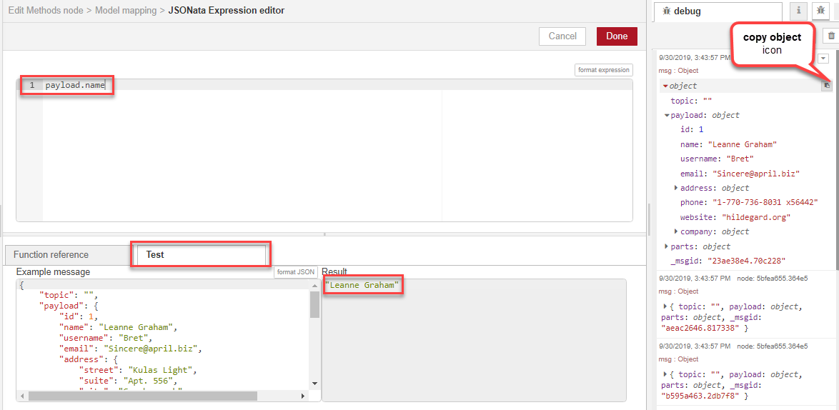
At this point we realise we can't use the address data in its current form for our Oracle table, as the address format is an object containing multiple lines, and our Oracle database requires it to be a single string. We need to concatenate the different address lines. This is where JSONata comes in. We choose the expression TypedInput and click the ellipsis button to open the JSONata editor.

We can use JSONata to manipulate the JSON object directly. First, we will click the Test tab and copy the message into the Example message window using the copy object icon and paste. We can now access the different parts of the message by typing the values in the editor and seeing the results displayed in the Result window.
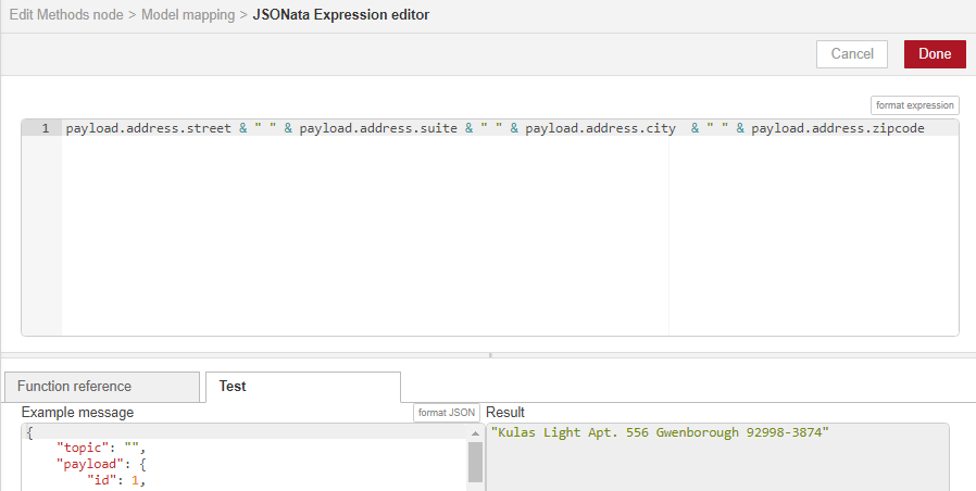
Once we have identified the different address lines, we use JSONata syntax to concatenate them, viewing the results of the transformation dynamically in the Result window.
Note: We are using JSONata to concatenate strings in this example, but there are many other types of transformations you can accomplish using JSONata. See the JSONata documentation for more details.
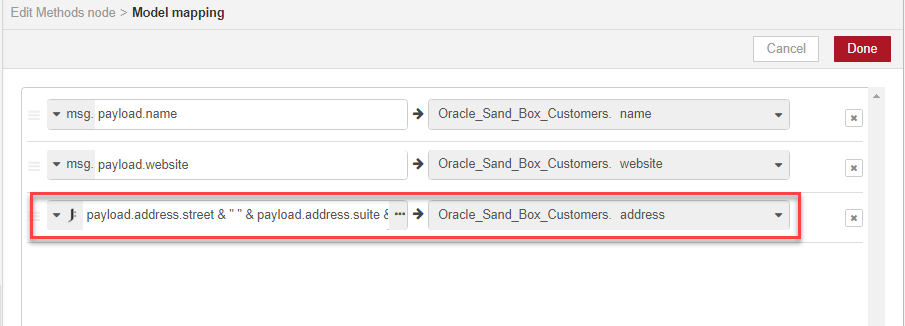
We click Done, and we can now see the JSONata concatenation expression in the Model mapping page, where the results of the JSONata concatenation map directly to the Oracle database address field.
We now have all the data flow elements we need. In this example we demonstrated the create method, but there is another method we could have used for mapping and inserting the data -- an upsertWithWhere method. The data mapping is created in exactly the same way as in the create method:
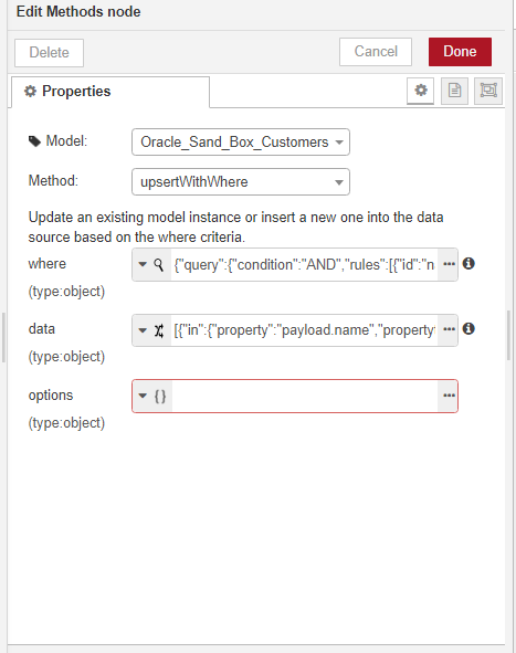
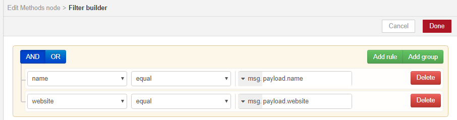
but we can also use the where clause to set field-level filters, so we can test for and update existing records in the Oracle table, rather than creating duplicates:
Step 4 - Deploy and test
Finally, we can deploy our new data flow -- success! We can see the concatenated address data in the debug pane.
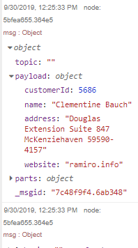
We can now make a test call to the REST ContactPlaceHolder API, and query the contacts Oracle database table exposed in the Oracle_Sand_Box_Customers data model, to make sure the new contact data was inserted into it.
Example 2
Extract data from a MongoDB database, transform it and insert it into an Oracle database using data from a second MongoDB database
In this example, we're going to show how to copy some customer orders from a MongoDB database to an Oracle database. You could use this, for example, if you needed to store some order data held by your customer in your own company's database. It is a little more complex than the previous example, as some data also needs to be retrieved from another table before the order data can be inserted into the Oracle table.
This example introduces the following concepts:
- the link node
- using additional nodes in your flow to gather data from multiple sources to help with data mapping and transformation
Before we begin
Before you read this example, you should familiarise yourself with the previous example, as this example builds on some of the concepts included in that one.
This example assumes the following data models were created in DIY:
- a MongoDB data model called Mongo_Sand_Box_NorthWind_Order:

- a MongoDB data model called Mongo_Sand_Box_NorthWind_Customer:

- an Oracle data model called Oracle_Sand_Box_Orders:

- an Oracle data model called Oracle_Sand_Box_Customers:

Step 1 - Retrieve the source orders and split the message
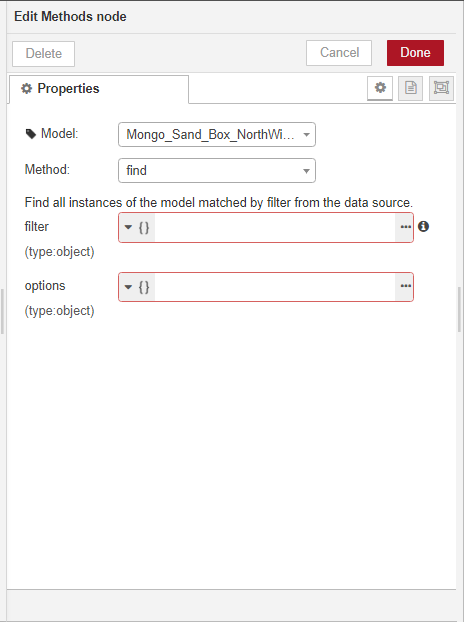
As in the previous example, we will retrieve records from the origin database and split the message into individual records. Since our data model is a MongoDB database, we need to explicitly execute a find method on it.
We won't go into too much detail on how to build the basic flow. You can have a look at the previous example if you need more guidance on this part.

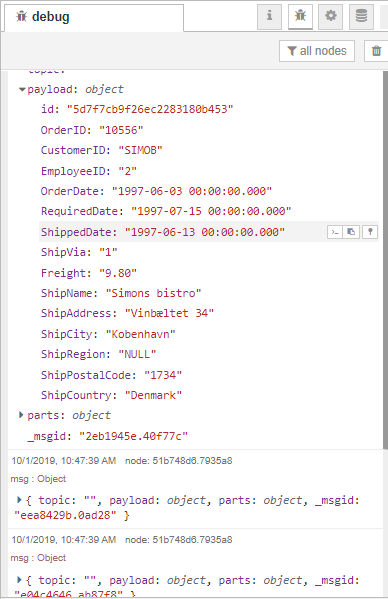
When we deploy the flow and click the timestamp node, we can see the split message in the debug pane.
Step 2 - Transform the order data and insert it into the Oracle database
As in the previous example, the next step is to add a create method (or you can also add an upsertWithWhere method, as explained in the previous example) to insert the data into the Oracle database.

We need to specify the field mapping for the method.

We can now deploy our flow and test it. However, our message output shows us something's wrong.
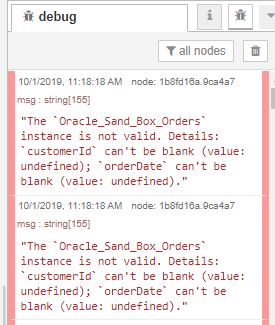
It looks like we need some more information.
Step 3 - Retrieve the customer data and insert it into the Oracle database
We need to start a new flow to retrieve the missing customer information and insert it into the Oracle customer database first. We first run a find method on the MongoDB customer database, then insert the records into the Oracle customer database.

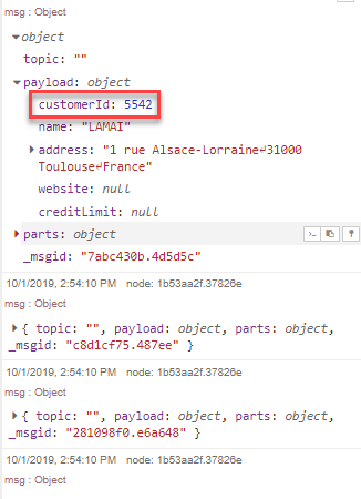
We can now deploy the flow, trigger it and look at the output. We can see the customerId field in the message.
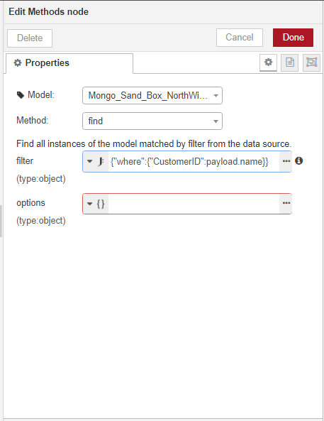
Step 4 - Use the customer ID to retrieve the order data
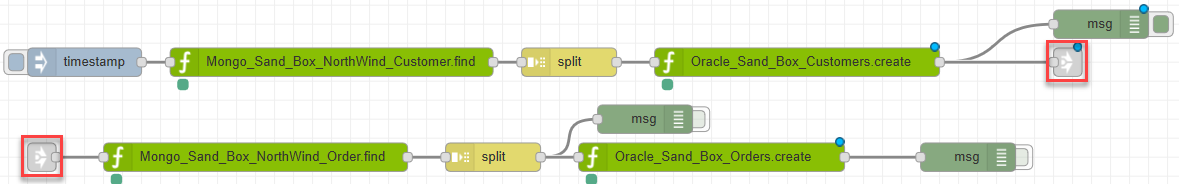
Now we'll add back in the flow from Step 2. Our flow is getting a little bit long, so we'll use the link node to continue it on another line.
We need to add the customer ID from Step 3 as a filter in the find method.
Step 5 - Deploy and test
We can now deploy the whole flow and test it.
Node reference
Here you can find a quick reference of each of the nodes available in the DIY data flow tool. You can find a more detailed description of each node type in the tool's info pane when you click on the node in the node palette, or in the Node-RED documentation.
| Node | Description |
|---|---|
| DIY nodes | DIY specific nodes |
| Methods | Execute a method on a DIY data model; different methods are available for different data model types |
| Hook end | Ends any one of the three following hook type nodes |
| Connector hooks | For acting on a DIY data source before or after running other methods on it -- for example, you can use a Connector hook followed by a change function to change the contents of a message; all subsequent operations performed on data models using the same data source invoke this hook first; always needs an accompanying Hook end node |
| Operation hooks | For acting on a DIY data model to create a global rule specifying how other methods can be run on it, for example, you can use an Operation hook followed by a change node to specify that all subsequent find methods must return data ordered in a particular way ; always needs an accompanying Hook end node |
| Remote hooks | Sane as Operations hooks, but only apply during API calls, not at method level as part of other data flows ; always needs an accompanying Hook end node |
| Storage watch | For interacting with Storage connector type data sources |
| input nodes | Nodes to input data into the next node in the flow |
| inject | For triggering a flow, including a payload type and whether the flow is to be automatically triggered at regular intervals |
| catch | For catching errors from one or more nodes |
| status | For reporting the status of one or more nodes |
| link | Used to split long flows into more than one line; this node restarts the flow on the new line (it needs a matching output link node to end the flow on the previous line) |
| function nodes | Nodes to execute a function against data passing through the node |
| function | For running a new JavaScript function |
| template | For setting properties based on a template (Mustache by default) |
| delay | For limiting the output rate |
| trigger | For triggering specific actions at time intervals |
| comment | For adding comments |
| switch | For routing the data to different flow branches based on test criteria |
| change | For modifying the data's properties and setting context properties |
| range | For mapping numeric data to a range |
| split | For splitting data into a sequence of messages |
| join | For joining sequences of messages into a single message |
| sort | For sorting data properties or sequences of messages |
| batch | For creating sequences of messages based on specific rules |
| html | For extracting HTML elements using a CSS selector |
| csv, json, xml, yaml | For converting strings in these formats to their JavaScript object representation |
| output nodes | Nodes to end a flow |
| debug | Used to display the flow output in the debug pane |
| link | Used to split long flows into more than one line; this node ends the flow on the first line (it needs a matching input link node to restart the flow on the new line) |